5G-Slicer Getting Started
This page includes information about deploying a simple application on 5G-Slicer plugin. Since we have already described the installation and deployment pipeline steps with Fogify Framework, in this part, we provide information about 5G-Slicer instantiation and modeling. For more information about the first three steps, you can go through our Fogify’s Getting Started guide.
Start 5G-Slicer GUI and Fogify Backend
5G-Slicer & Fogify Services
As we described before, one has to install the preconditions of Fogify and, for multi-host execution, to build a docker swarm cluster. Then, the easiest way to start the 5G-Slicer is to download its code from github repo, build the 5G-Slicer container by running the following command:
docker-compose build
And then, user can start the 5G-Slicer in docker-compose mode by running the following command in the project’s folder.
sudo docker-compose -p 5gslicer up
Especially, the docker-compose.yaml file of the project is the following and includes both 5G-Slicer service
and the Fogify services (Controller, Agent, Monitoring).
We should note here that users need to define some parameters at the .env file and
can find them in Fogify’s installation guide.
version: '3.7'

services:

  ui:
    build: .
    image: fogemulator/5g-slicer-jupyter:v0.01
    volumes:
      - ./:/home/jovyan/work
    ports:
      - 8888:8888
      - 5555:5555
    environment:
      - "JUPYTER_ENABLE_LAB=yes"
      - "GRANT_SUDO=yes"
    user: root
    command: ['start.sh', 'jupyter', 'lab']
  controller:
    image: fogemulator/fogify:v0.02
    entrypoint: [ "python", "/code/fogify/main.py", "--controller"]
    volumes:
      - /var/run/docker.sock:/var/run/docker.sock
      - /usr/bin/docker:/usr/bin/docker
    ports:
      - 5000:5000
    extra_hosts:
      - ${MANAGER_NAME}:${MANAGER_IP}
    environment:
      CPU_OVERSUBSCRIPTION_PERCENTAGE: ${CPU_OVERSUBSCRIPTION_PERCENTAGE}
      RAM_OVERSUBSCRIPTION_PERCENTAGE: ${RAM_OVERSUBSCRIPTION_PERCENTAGE}
      CPU_FREQ: ${CPU_FREQ}
      HOST_IP: ${HOST_IP}
      NAMESPACE_PATH: ${NAMESPACE_PATH}
      SNIFFING_ENABLED: ${SNIFFING_ENABLED}
      SNIFFING_PERIOD: ${SNIFFING_PERIOD}
      CONNECTOR: ${CONNECTOR}
      MANAGER_IP: ${MANAGER_IP}
      MANAGER_NAME: ${MANAGER_NAME}
  agent:
    image: fogemulator/fogify:v0.02
    entrypoint: [ "python", "/code/fogify/main.py", "--agent", "--agent-ip", "${HOST_IP}"]
    extra_hosts:
      - ${MANAGER_NAME}:${MANAGER_IP}
    volumes:
      - /var/run/docker.sock:/var/run/docker.sock
      - /usr/bin/docker:/usr/bin/docker
      - /proc/:${NAMESPACE_PATH}
      - /var/run/docker/:/var/run/docker/
      - /sys/class/net/:/sys/class/net/
      - /lib/modules:/lib/modules
      - /sbin/modprobe:/sbin/modprobe
      - /usr/lib/tc:/usr/lib/tc
    privileged: true
    cap_add:
      - ALL
    depends_on:
      - cadvisor
      - controller
    ports:
      - 5500:5500
    environment:
      CONTROLLER_IP: ${MANAGER_IP}
      HOST_IP: ${HOST_IP}
      CPU_FREQ: ${CPU_FREQ}
      NAMESPACE_PATH: ${NAMESPACE_PATH}
      SNIFFING_ENABLED: ${SNIFFING_ENABLED}
      SNIFFING_PERIODICITY: ${SNIFFING_PERIODICITY}
      CONNECTOR: ${CONNECTOR}
      MANAGER_IP: ${MANAGER_IP}
      MANAGER_NAME: ${MANAGER_NAME}
  cadvisor:
    image: gcr.io/google-containers/cadvisor:latest
    volumes:
      - /:/rootfs:ro
      - /var/run:/var/run:ro
      - /sys:/sys:ro
      - /var/lib/docker/:/var/lib/docker:ro
      - /dev/disk/:/dev/disk:ro
    ports:
      - 9090:8080
    expose:
      - 8080
      - 9090
5G-Slicer GUI
Similarly with Fogify, 5G-Slicer provides the SlicerSDK (equivalent to FogifySDK).
5G-Slicer exposes the SlicerSDK capabilities via Jupyter interface (ui service of the docker-compose.yaml).
Furthermore, SlicerSDK offers a wide range of new visualisations (like interactive maps) and programming functions(e.g. move ad-hoc actions and trajectories).
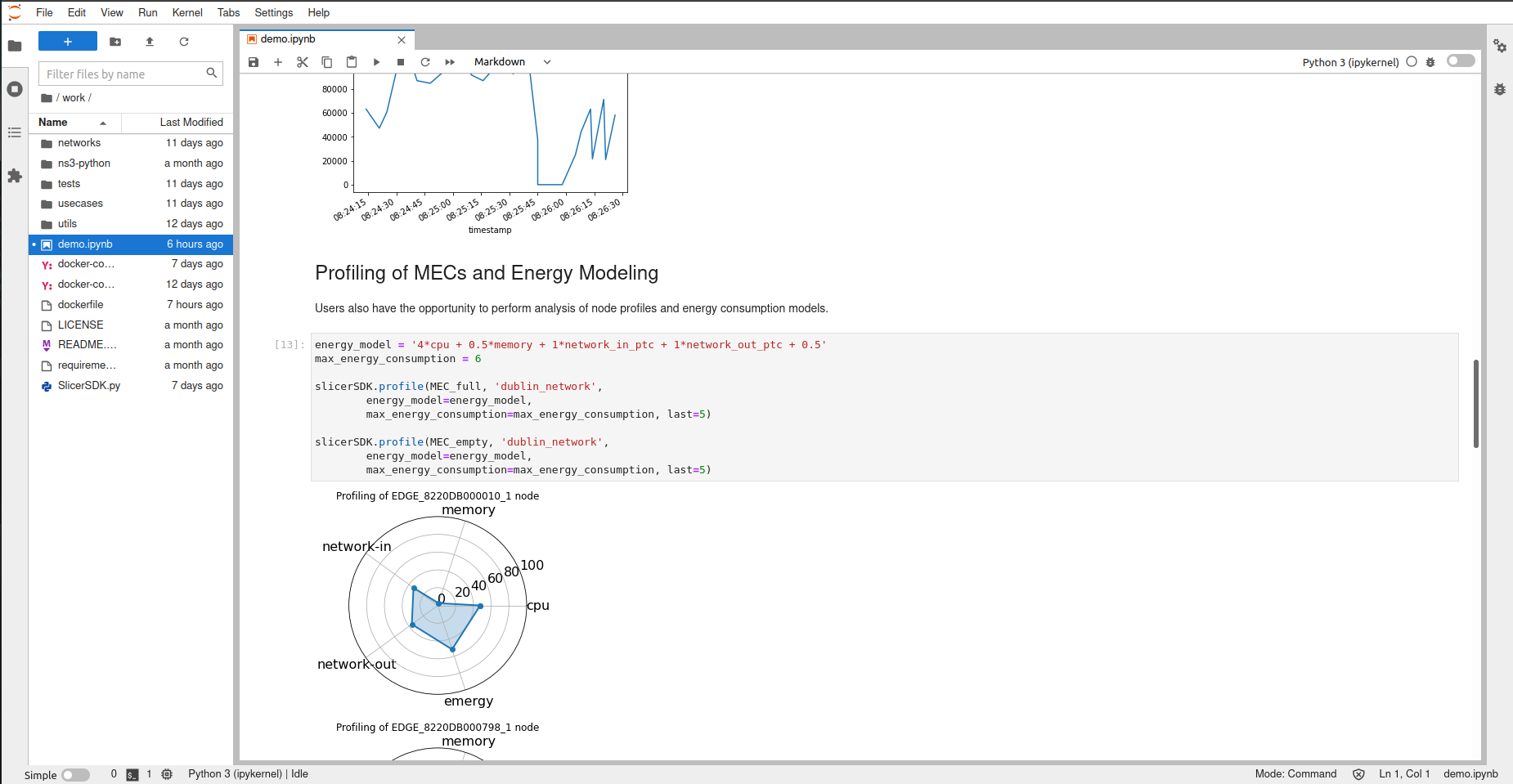
The following image is a snapshot of the SlicerSDK jupyter-enabled interface.
5G-Slicer Model Example
Next, let us introduce a modeling example of an application.
Application Model
As we described in Fogify’s getting started guide, users describe their application via docker-compose files. Following yaml file depicts an example of a such application.
version: '3.7'
services:
  cloud_service:
    image: bus-exp:0.0.1
  edge_service:
    image: bus-exp:0.0.1
  bus_service:
    image: bus-exp:0.0.1
    environment:
      - "NODE_TYPE=IOT_NODE"
    volumes:
      - "/home/ubuntu/data:/data"
5G-Slicer-enriched Fogify Model
Fogify base model
With the docker-compose to be ready, users need to add Fogify’s extra fields, namely, nodes, networks and topology.
The following example illustrates the high-level structure of an Fogify’s infrastructure topology.
...

x-fogify:
    nodes:
        ...
    networks:
        ...
    topology:
        ...
Nodes are inherited from Fogify’s model and there is no change in the 5G-Slicer model.
5G Network Slice description
In 5G-Slicer, users can describe network slices, under the network field.
Specifically, a slice includes radio units (RUs) locations, midhaul_qos and backhaul_qos that are the QoS characteristics for midhaul
(RU-to-RU and Edge-to-edge connections), wireless connection type (wireless_connection_type) like MIMO, and
its parameters (parameters).
  - network_type: slice
    name: edge-net-1
    midhaul_qos:
      latency:
        delay: 3ms
        deviation: 1ms
      bandwidth: 100mbps
    backhaul_qos:
      latency:
        delay: 30ms
        deviation: 1ms
      bandwidth: 100mbps
    wireless_connection_type: MIMO
    parameters:
      transmit_power: 30  # dbm
      carrier_frequency: 28  # gigahrz
      bandwidth: 100  # megahrz
      UE_noise_figure: 7.8  # db
      RU_antennas_gain: 8 # db
      UE_antennas_gain: 3 # db
      maximum_bitrate: 538.71
      minmum_bitrate: 53.87
      queuing_delay: 2 # ms
      RU_antennas: 8
      UE_antennas: 4
    RUs:
      - lat: 35.14996886033924
        lon: 33.410295020090246
Topology
Finally, users can introduce the topology primitive, which interconnects services, nodes, and networks (slices).
Specifically, a topology is a set of blueprint objects.
5G-Slicer extends the blueprint definition with the location field
that could include latitude(lat), longitude(lon), and altitude(alt in meters).
Furthermore, users should provide the location_type that is either UE(user equipment), EDGE, or CLOUD.
We should note here that if the location_type is CLOUD, users should not provide geolocation, and
if there is no RU at the coordination of the EDGE, the system creates automatically an RU at this place.
  topology:
  - label: cloud-server
    networks:
    - edge-net-1
    node: cloud-server-node
    replicas: 1
    service: cloud-server
    location:
      location_type: CLOUD
  - label: mec-svc-1
    networks:
    - edge-net-1
    - internet
    node: edge-node
    replicas: 1
    service: mec-svc-1
    location:
        lat: 35.14996886033924
        lon: 33.410295020090246
        location_type: EDGE
  - label: mec-svc-2
    networks:
    - edge-net-2
    - internet
    node: edge-node
    replicas: 1
    service: mec-svc-2
  - label: car-workload-1
    networks:
    - edge-net-1
    - internet
    node: car-node
    replicas: 1
    service: car-workload
    location:
        lat: 35.14996886033924
        lon: 33.410295020090246
        alt: 5
  - label: car-workload-2
    networks:
    - edge-net-2
    - internet
    node: car-node
    replicas: 1
    service: car-workload
Trajectories
Trajectories in 5G-Slicer extend the scenario primitive of the Fogify’s model.
Specifically, a trajectory is a sequence of moving actions that the system translates then into low-level network updates.
For instance, the following trajectory (mobility_scenario) moves the car-workload-1 in different location during the experimentation.
  scenarios:
  - name: mobility_scenario
    actions:
    - time: 10
      position: 0
      instance_type: car-workload-1
      instances: 1
      action:
        type: move
        parameters:
            network: edge-net-1
            lat: 35.15091624851098
            lon: 33.408127726284306
    - time: 10
      position: 1
      instance_type: car-workload-1
      instances: 1
      action:
        type: move
        parameters:
            network: edge-net-1
            lat: 35.15192942739787
            lon: 33.405751258916474
    - time: 10
      position: 2
      instance_type: car-workload-1
      instances: 1
      action:
        type: move
        parameters:
            network: edge-net-1
            lat: 35.15285486445768
            lon: 33.40372880297997
    - time: 10
      position: 3
      instance_type: car-workload-1
      instances: 1
      action:
        type: move
        parameters:
            network: edge-net-1
            lat: 35.15396009516559
            lon: 33.401346833487295
Experimentation and Metrics
Deployment
The following lines of code illustrate the use of SlicerSDK (which is an extension of the FogifySDK).
Specifically, the user imports the SDK, constructs a 5G-Slicer object, which encapsulates information about the Fogify’s controller url
and the 5G-Slicer-enabled topology description file (docker-compose.yaml). Lastly, when one executes the deploy function, the sdk submits the description to the fogify’s Controller.
from SlicerSDK import SlicerSDK
slicer_sdk = SlicerSDK("http://controller:5000","docker-compose.yaml")

slicer_sdk.deploy()
5G-Slicer displays a progress bar during the submission process.
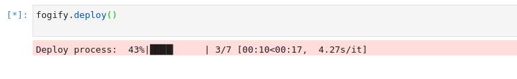
At the end, when the deployment is over, the system generates a simple message to the end-users.

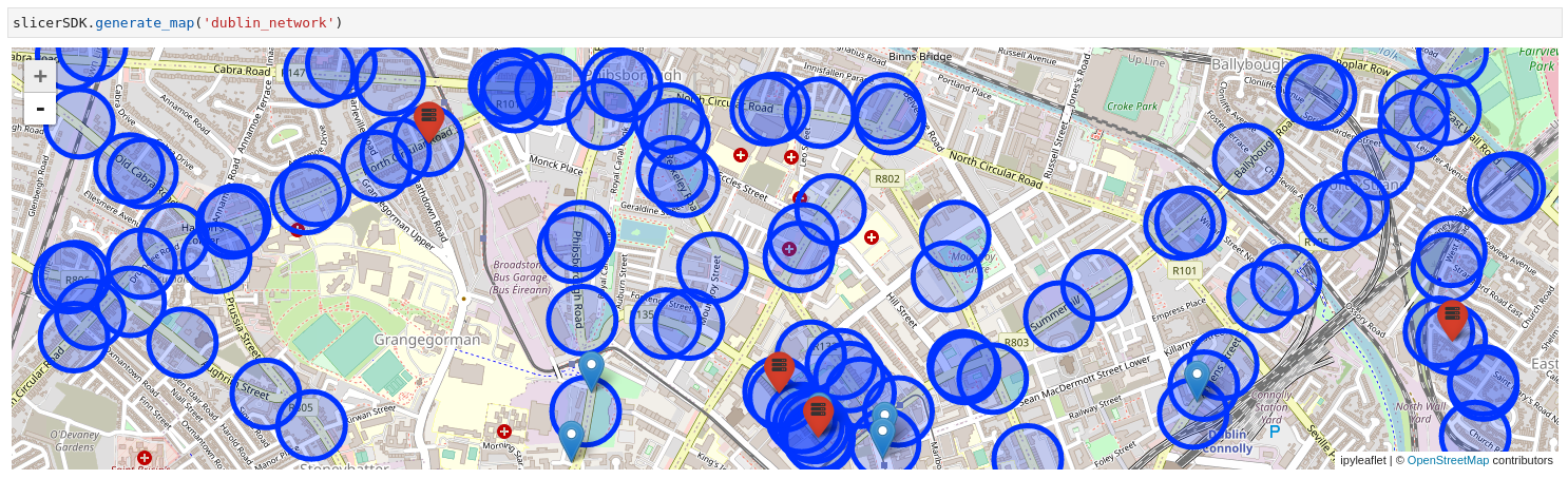
Interactive Map
5G-Slicer provides an interactive map that depicts the positions of mobile nodes (blue markers), edge modes (red markers), and the network coverage (blue circles). Furthermore, users can move the mobile nodes (blue markers) and the system will update the connectivity of the moving node.
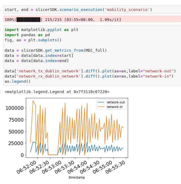
Run Mobility Scenario
The mobility scenarios extend the scenario primitive of Fogify model and execution. During the mobility scenario execution, the movement of the mobility nodes can be seen on the interactive map. When a mobility scenario is finished, users can request the monitoring data via the start and end time of the scenario. The following plot illustrates an example of network ingoing and outgoing traffic generated after the execution of a mobility scenario.